Screen space directional occulusion
This Section is dedicated to document my partial implementation of a research paper called "Approximating Dynamic Global illumination in Image Space"
Context:
This project was done while taking the Image Synthesis course at "Ecole polytechnique". In this course I had the opportunity to go through the main principles, algorithms and techniques for image synthesis. In particular, I had to deal with digital models of shape, appearance, lighting and sensors presents in a 3D scene. I got familiar with the rendering equation as well as the standard illumination, shading and reflectance models. Within this course, I also encountered various rendering algorithms like projective rendering and ray tracing.
I) Paper Summary:
The paper I studied is entitled “Approximating Dynamic Global illumination in Image Space” written by Ritschel, Tobias, Thorsten Grosch, and Hans-Peter Seidel. The paper suggests that by using the same technique of the SSAO [Shanmugam and Arikan 2007] they could compute many more types of effects. Specifically, in this paper they developed an overhead on the previous SSAO standard technique. They proposed a technique that approximates direct and one-bounce light transport in screen space. The paper suggests a technique called screen-space directional occlusion (SSDO) That accounts for: the direction of the incoming light-one bounce of indirect illumination- reducing the computation time.
a) Near-field Light Transport in Image Space:
Their work makes better use of the information that is already computed during the SSAO process and extracts two more significant effects: direction occlusion and indirect bounces.
Direction lighting using directional occlusion:
For this part, the authors proposed to remove the decoupling of occlusion and illumination present in the standard SSAO in the following way:
For every pixel at 3D position P with normal n, the direct radiance Ldir is computed from N sampling directions Wi uniformly.
distributed over the hemisphere, each covering a solid angle of
For the indirect bounce of light, they use the information stored after the previous light pass to combine it with the occluders (V=0).
To calculate the visibility V, the paper uses the same technique of the SSAO. They calculate random offsets around the point P in view space. Then by applying depth tests in screen space, they can determine which one of the offsets will be considered as occluder (V=0).
b)Single-depth Limitations:
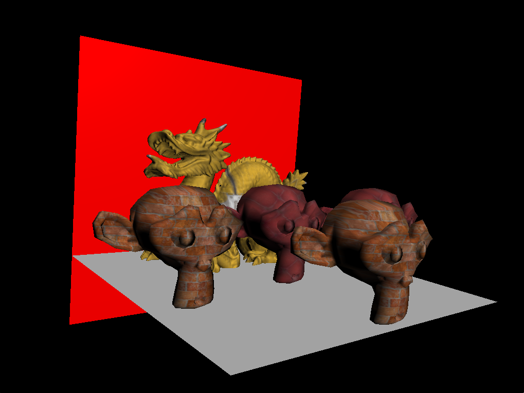
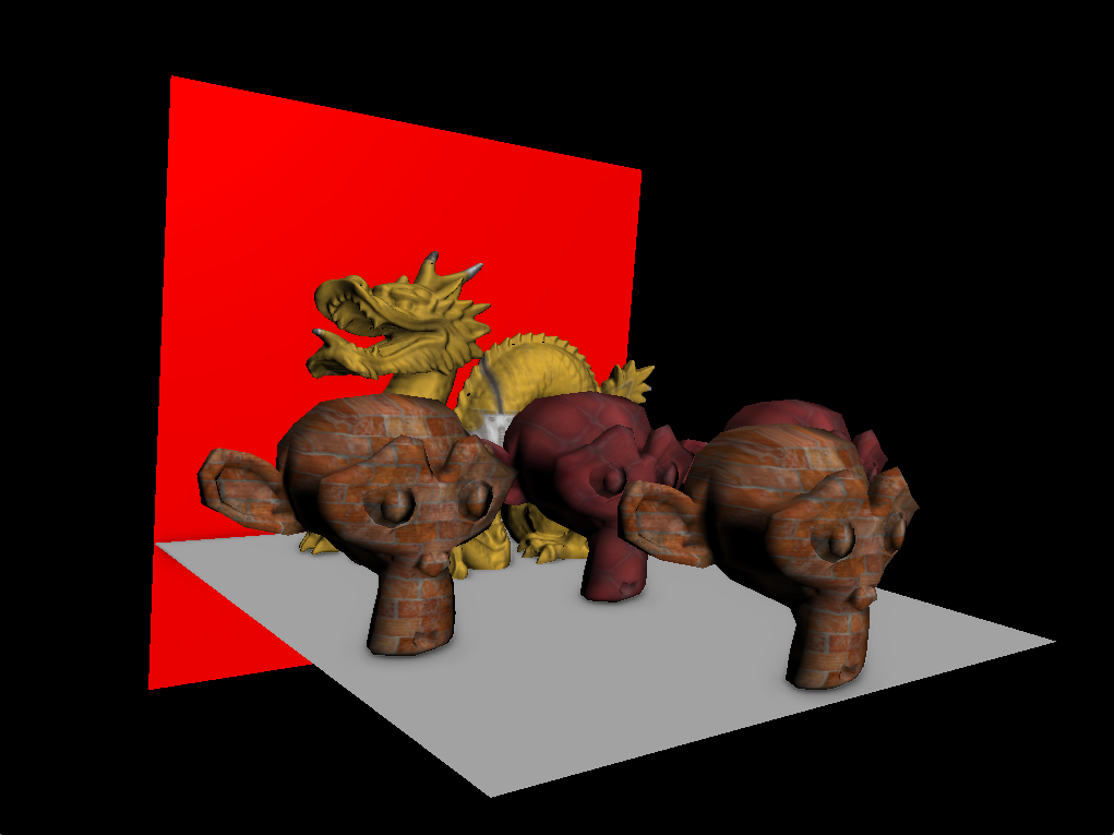
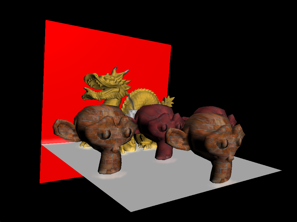
The visibility test explained in the previous part is an approximation since depth tests are applied in screen space. Meaning, it doesn't take in consideration the geometry of the mesh. With this constraint they got two issues that need to be handled. I am going to detail both in the coming parts. First issue; In certain view angles the source of a given color bleeding is occluded. So the information about its color in the screen space is lost. Thus the coloring bleeding disappears in that region. You can see this effect in the version that I implemented (see picture below) where the color of the ground doesn't bleed on the red wall.
A solution, provided in the paper, consisted in using multiple cameras. The multiple first light passes of each camera will give us information to reconstruct the color bleeding effect lost with a single camera. The authors propose that the best possible viewpoint for an additional camera would be completely different from the viewer, like rotated about 90 degrees around the object center to view the grazing-angle polygons from the front. The Second issue, that the SSDO may encounter at this stage, is that: if there is another geometry that can interfere in the occlusion test performed before (like in the case of point A (relative to P)) in the figure provided in the paper.
To overcome this limitation, the authors resorted to the depth peeling technique [Everitt 2001]. Extending the depth tests not only to the first layer but to ‘n’ layers, improves the blocker test (visibility test) since it provides more information about the geometry of the scene. Like in the case of a two-manifold geometry; The first and the second layer correspond to the front and back face of the volume, so an offset found between these two layers is inside the mesh.
c)Integration in Global Illumination:
SSDO can be used for natural illumination. The basic idea is to first compute the global illumination on a coarse representation of the geometry.
Then, to add the lighting to the screen space at runtime.
One of the results they showed is an example of Instant Radiosity with shadow correction and an additional indirect bounce in screen space.
II) My implementation:
Before going through the details of the implementation, I want to point out that my work consists in implementing the standard SSDO. Meaning, the goal of my implementation is to have only a color bleeding effect without further enhancements mentioned in the paper. In order to fully grasp the mechanism of the SSDO technique I had to go through the SSAO in the first place. Because a large part of the idea behind the SSDO came from it. And for that, I had to get familiar with the deferred shading techniques. Thus, I decomposed my work into 3 milestones:
First milestone was to render the same result of the lab by deferred rendering. Second milestone was to implement the SSAO technique to understand the blocker test mentioned in the paper. Third and last milestone, using what I learnt from the previous steps I will implement SSDO.I provided in the demo provided in the github link 3 buttons (F1,F2,F3) to switch between the results of my 3 milestones.
1)Deferred Shading:
In order to apply lighting to the scene, a forward rendering technique is usually opted. But sometimes with the presence of a big number of point lights this technique may hinder the performance. This is mainly due to the large number of objects iterated on, for each active light. Deferred Shading technique in this case can come in handy. By decoupling the geometry from light’s calculation, much more performance is gained. That’s because the calculations are constrained to the screen space. Deferred Shading consists of two passes: the first one is the geometry pass. This pass renders the scene one time and can store all kinds of geometrical information in the process (like normals,positions..). With this way, I drastically reduce the number of calculations done in the second pass which is the lighting pass. In fact, this pass constructs the lighting by retrieving the necessary information stored in the geometry buffer. I also want to add that the deferred shading technique can be combined with forward rendering. It requires only copying the depth buffer of the geometry pass to the forward rendering one. I didn’t implement this combination being not very crucial for my ultimate goal.
Implementation Details:I implemented a class called “DefferedRenderer” where I will handle all rendering processes in my project. In this class, I start by initializing the textures and the buffers that I am going to use. First, I load the albedo and roughness texture used in the scene. Secondly, I generate the frame buffers and the textures associated. In order to render the scene like in the forward rendering one, I needed to retrieve the position of fragments in view space + normals in global space +colors. Then I applied the standard light calculations. As a summary, I used one more frame buffer to reach my goal. In other parts, I will show how I use multiple frame buffers for more complex calculations. The ‘F1’ button will enable the standard deferred renderer with 32 random directional light sources.
2) SSAO:
In order to perform screen space ambient occlusion, I had to approximate for each fragment in the screen the number of occluders nearby.
a)Blocker test:
I considered a hemisphere tangent to the fragment in the view space and N number of samples randomly generated inside of it. In my implementation, I also aligned the samples to be to the center of the hemisphere. Besides, I needed to choose randomly an orientation for the hemisphere, for that I generated a 4*4 noise texture in order to generate the tangent vector later in the fragment shader (the noise texture is scaled in the fragment shader to fit the sceen’s width & height).
b)Calculate ambient occlusion:
In the fragment shader, I iterate on all the samples for each fragment and accumulate the number of occluders by performing a depth test in screen space between the sample and the fragment (in the same place of the screen) retrieved from the geometry pass. I also constrain the effect of ambient occlusion to the hemisphere already described by simply performing a range check (to avoid applying SSAO on a far geometry). The resulting texture contains a lot of noise, so I added a blurring pass by convolving a gaussian kernel (4x4) on the resulting SSAO texture.
c)Lighting pass:
After calculating the number of occluders per fragment, I perform the lighting pass described in section II.1 but with one minor change. I multiplied the diffuse light by the ambient occlusion stored in the blurring pass.
Implementation Details:For each pass I perform, I need a frame buffer and the texture associated. This texture will be the link between each layer of the rendering process. I will detail the parameters I picked for The texture of the framebuffers. The geometry texture parameters:
Gl_ClAMP_TO_EDGE was added to the position buffers to avoid over sampling when retrieving the texture later. Fragment/VertexShaders associated with this part: SSAO_g_buffer,SSAO_FS,SSAO_BLURFS,LightingSSAOFS. Each other texture I created had the same parameters as the normals. You can check the result of my SSAO by clicking on F2.
3) SSDO:
In order to perform SSDO, I used the same technique described in the previous sections. But now for each occluder, I transmitted its color to the center of the hemisphere. The transmission of color or as the authors call it in the paper “color bleeding” is weighted by a user-controllable coefficient, the cosine of the angles (between the normals of receiver/sender and the transmittance) and its distance to the center.
Implementation Details:In this part, I will also use the same deferred shading techniques I described in previous sections. That’s why I will go through only the different framebuffers and passes I performed to reach the result.
First pass: The same geometry pass I performed for the SSAO.
Second pass: Lighting pass to retrieve the correct colors used later in the color bleeding.
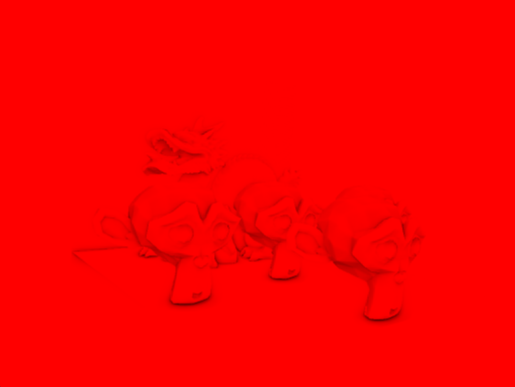
Third pass: In this pass, I calculate only the indirect bounces of light on each fragment of the screen by using
the same technique of the SSAO. In this part, I changed a bit the formula proposed in the paper because the resulting
color bleeding was very intense (in my case). I used this formula instead:  Then, I averaged all the indirect bounces of light and multiplied it by a floating number ‘control’ that can be adjusted by the user.
Forth pass: After storing the result of the third pass in a texture,
I had to perform a blurr pass to the results like I did in the SSAO but this time I used a bigger gaussian kernel 8x8.
III) Results & Limitations:
Down below you will see real time snippets of the scene I created. There are also different results of different parts of the implementation.
Limitations: -The code that I implemented doesn’t support window resize. -Color bleeding might disappear in grazing view angles of the scene (like shown in “I / b)” ) -With some distribution geometry, we can notice the importance of the depth peeling technique.


